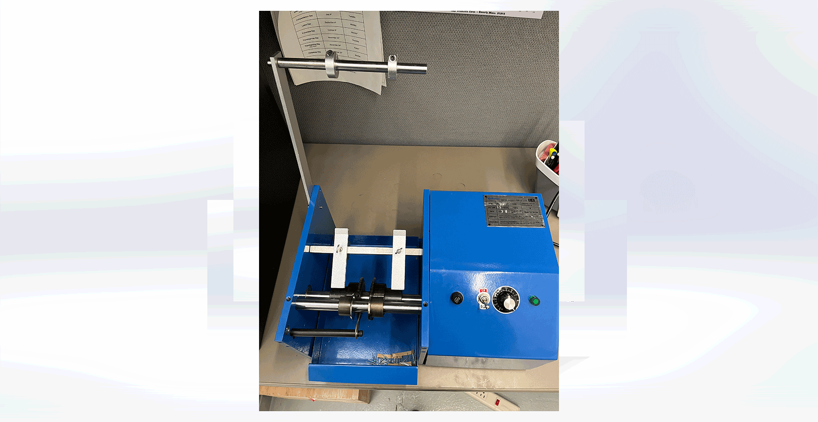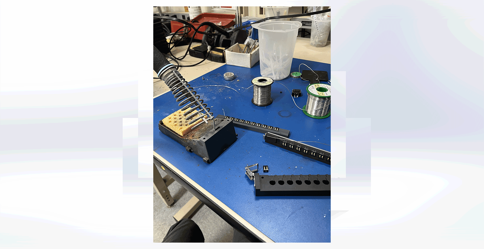

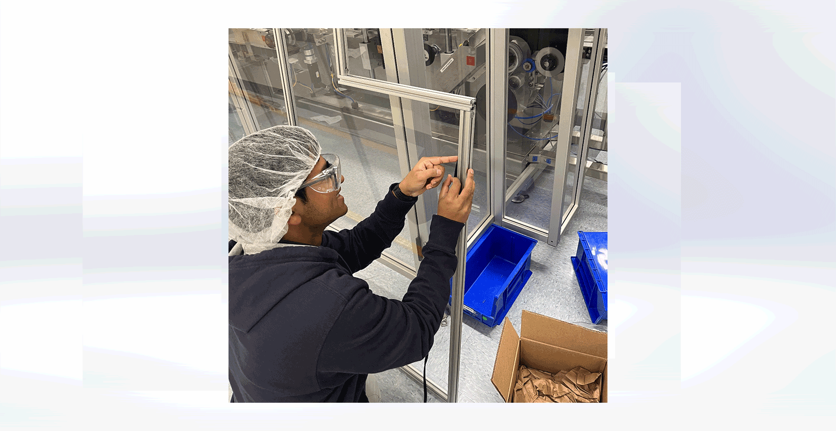
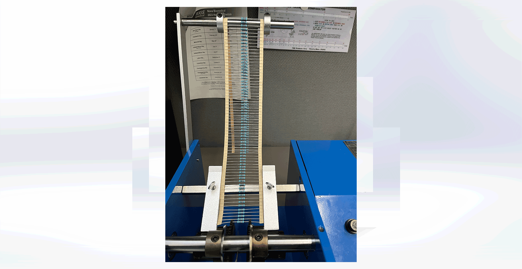
In the latter part of my co-op, I addressed the manual cutting challenges in the sensors and tubing department by introducing an automated solution – the RS-904I resistor cutter from RKens. Assembling the device with RKens' components, I developed operating instructions, a maintenance procedure, and conducted preventative measures. After validating its performance, I initiated the training of department employees on its usage. The automated resistor cutter not only reduces wrist fatigue but also enhances overall efficiency in resistor lead cutting processes, marking a significant improvement in the department's workflow.
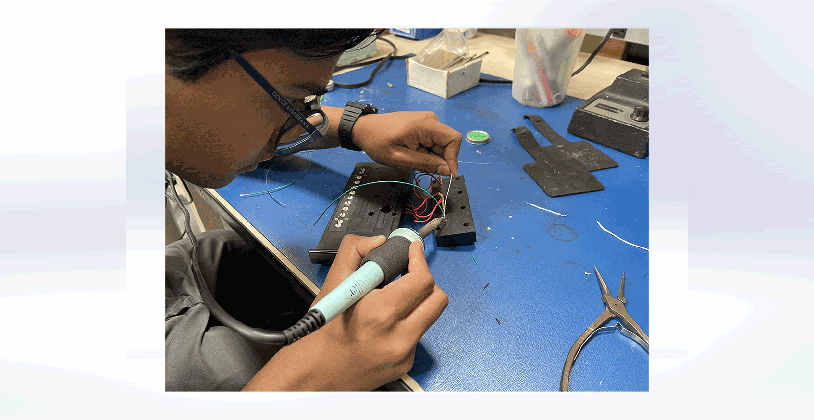
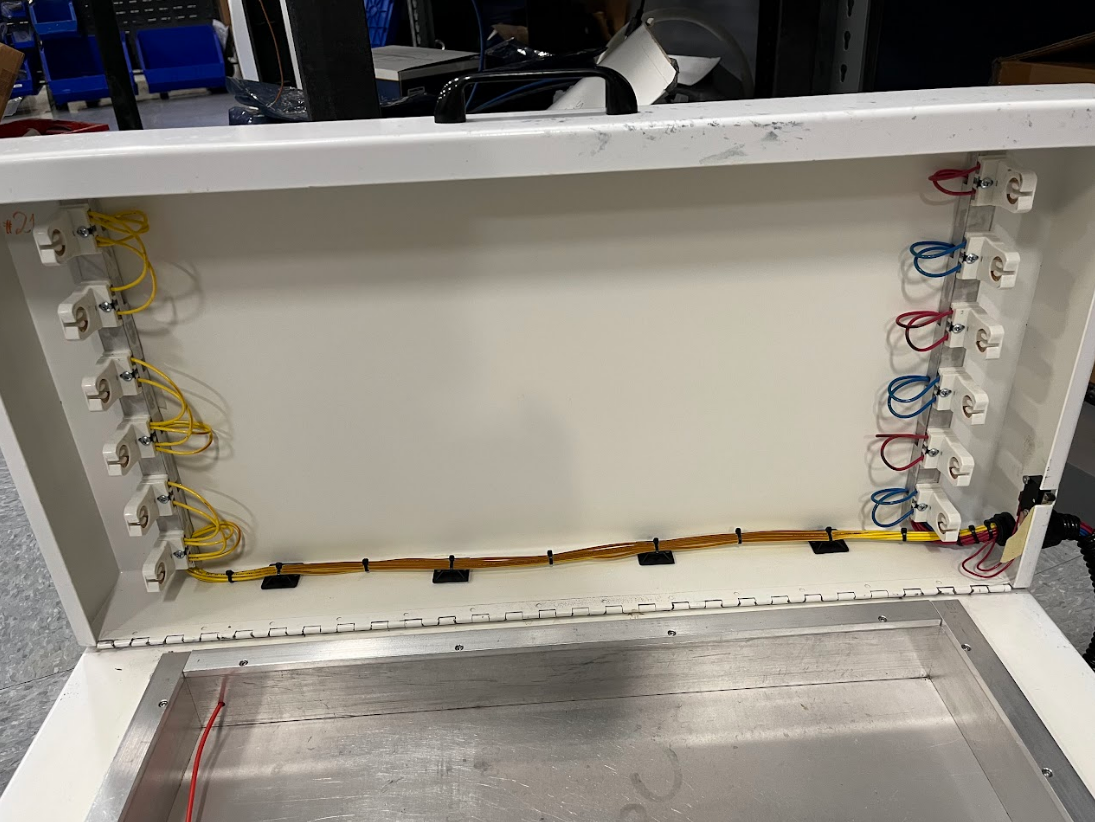
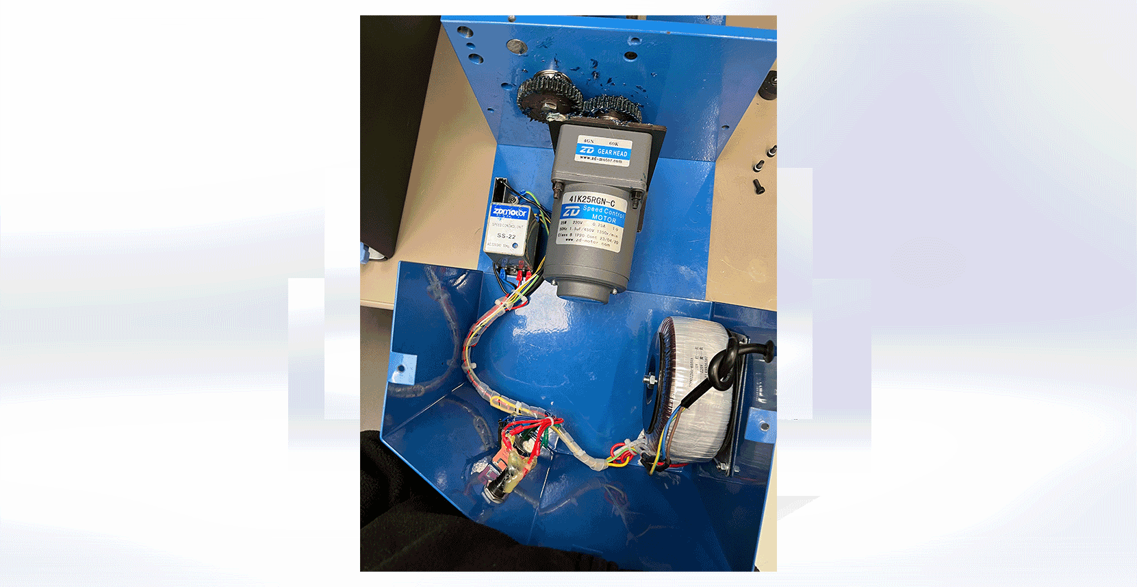
Interior Electronic Assembly
Video Demo
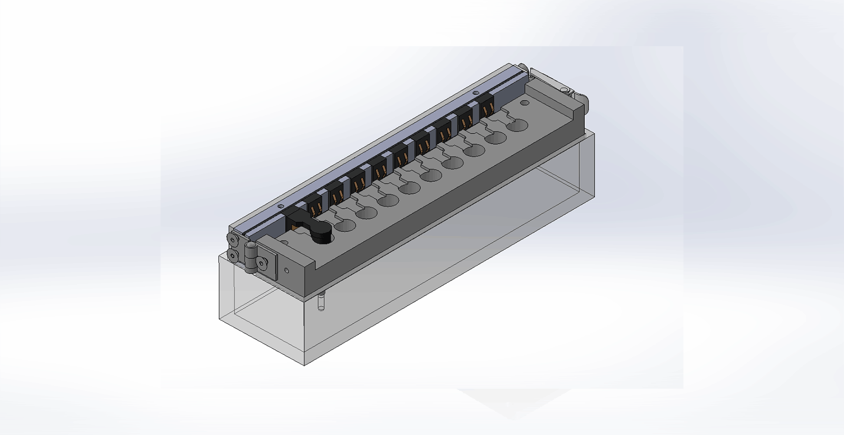
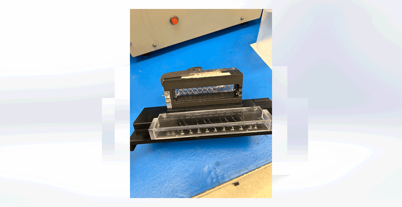
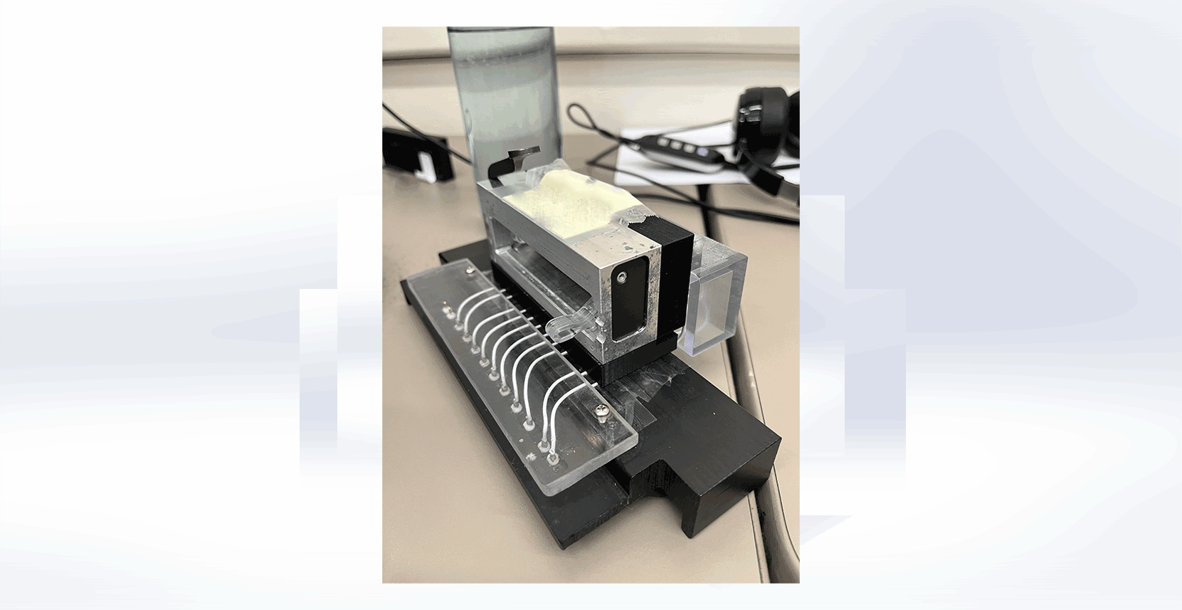
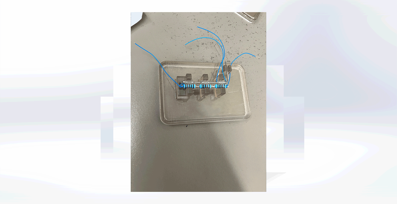
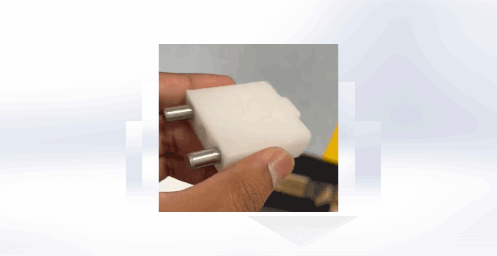
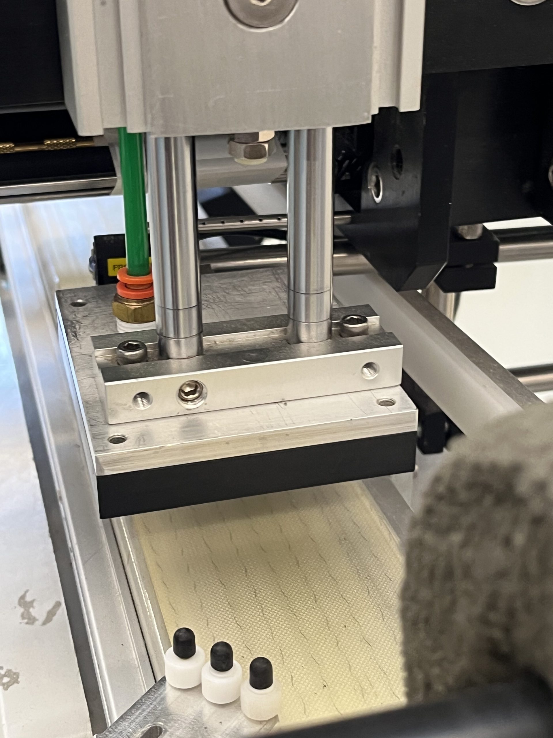
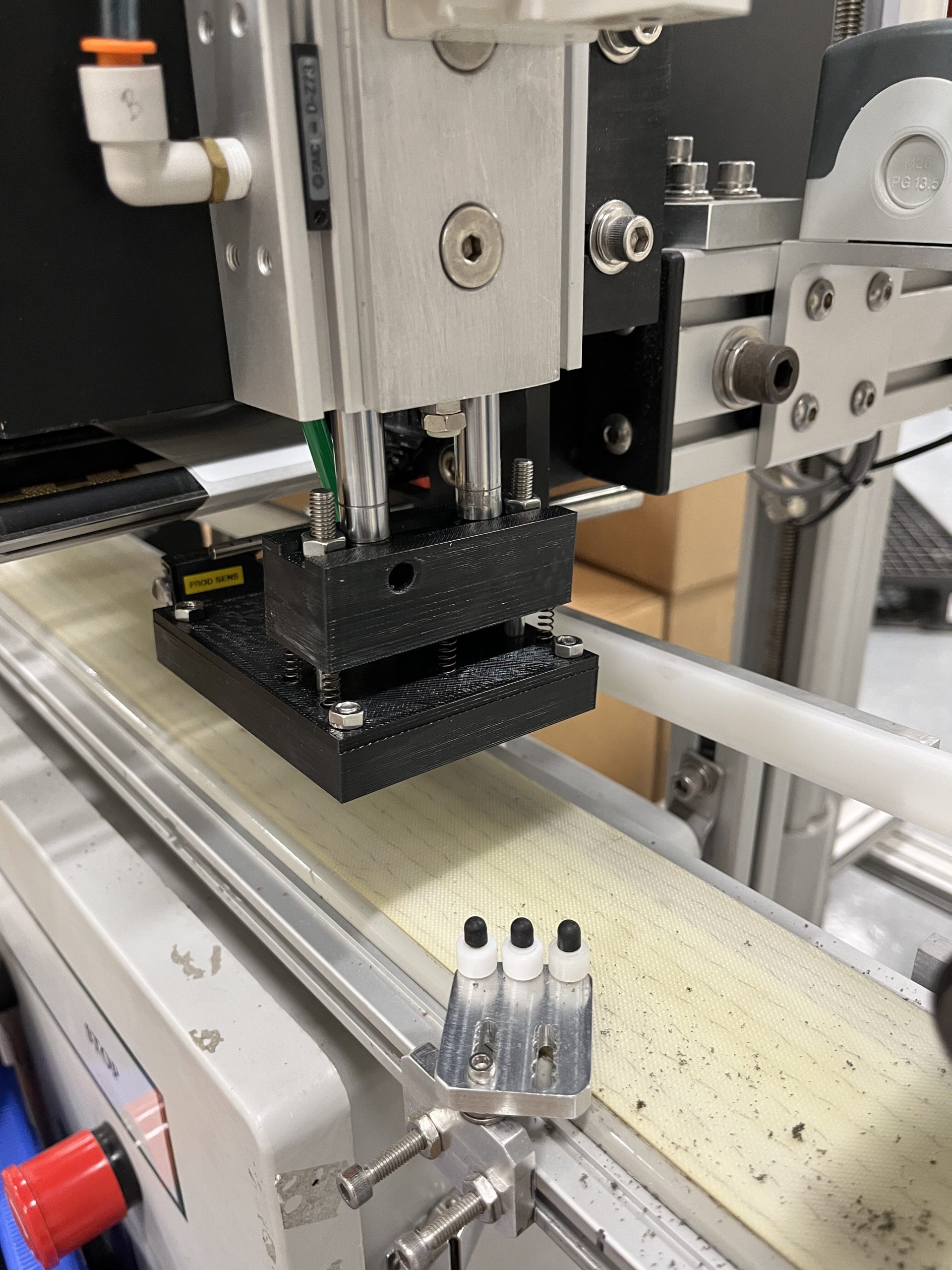
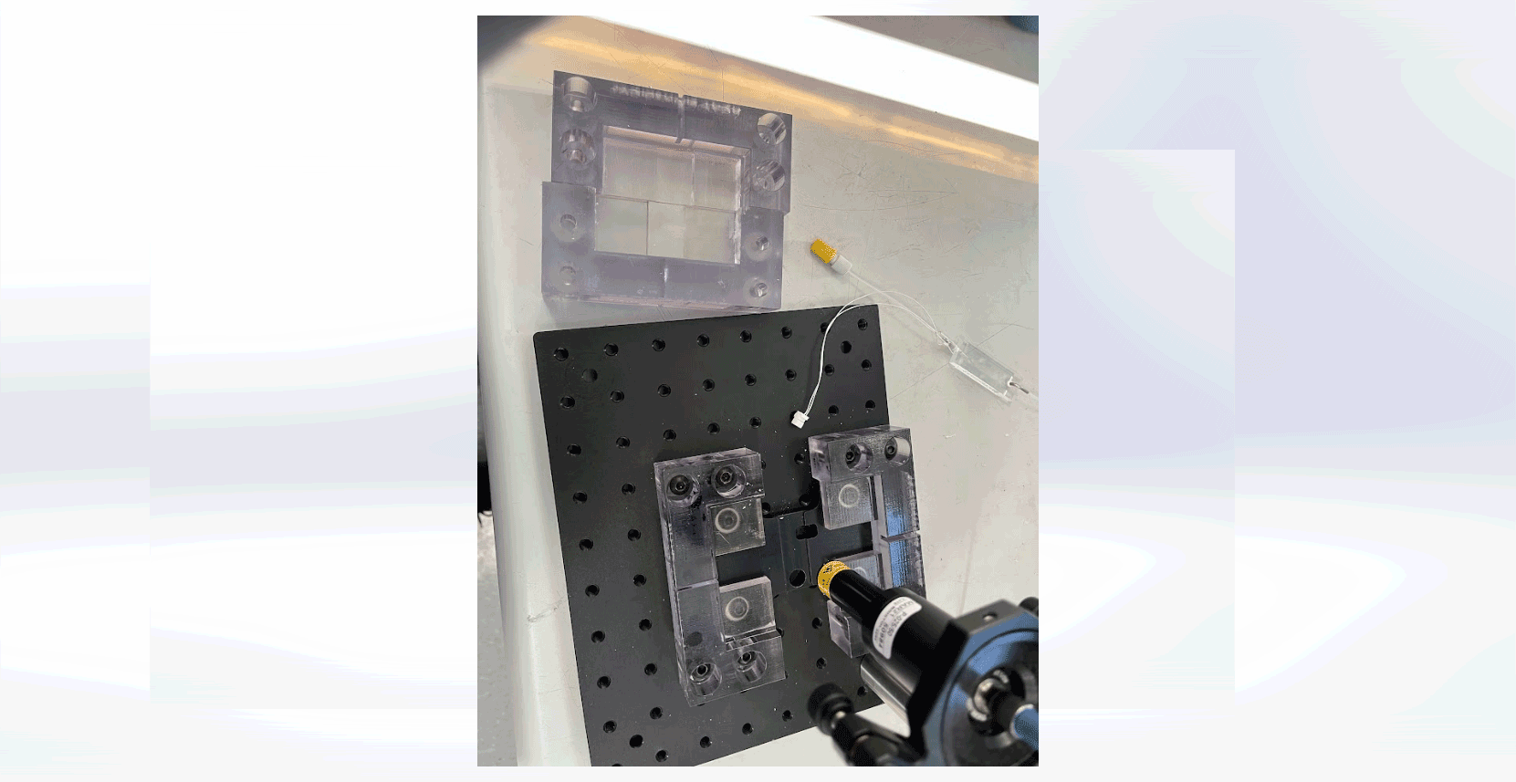
Resistor Cutter with Taped Resistors
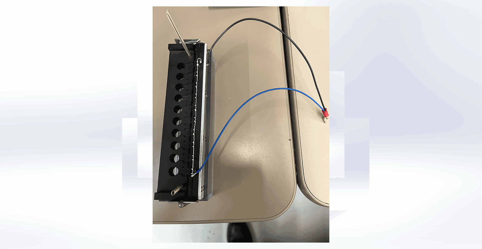
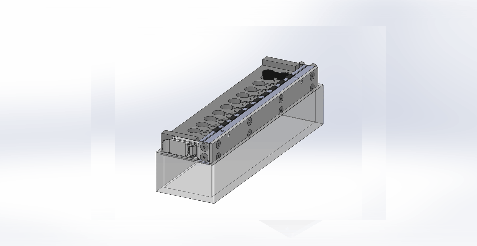
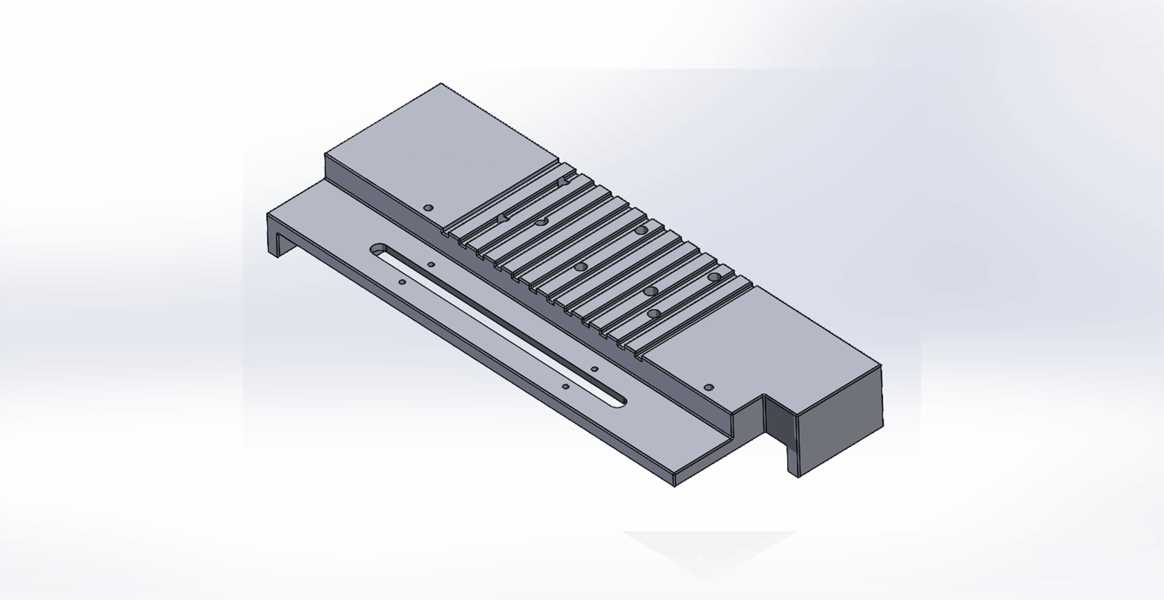
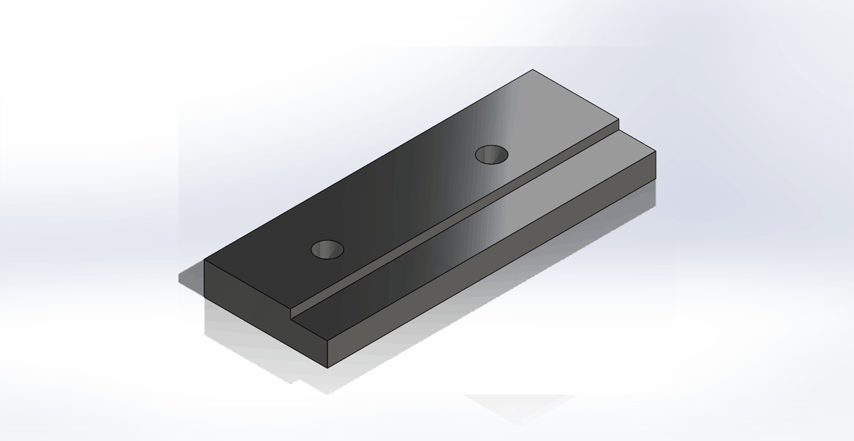
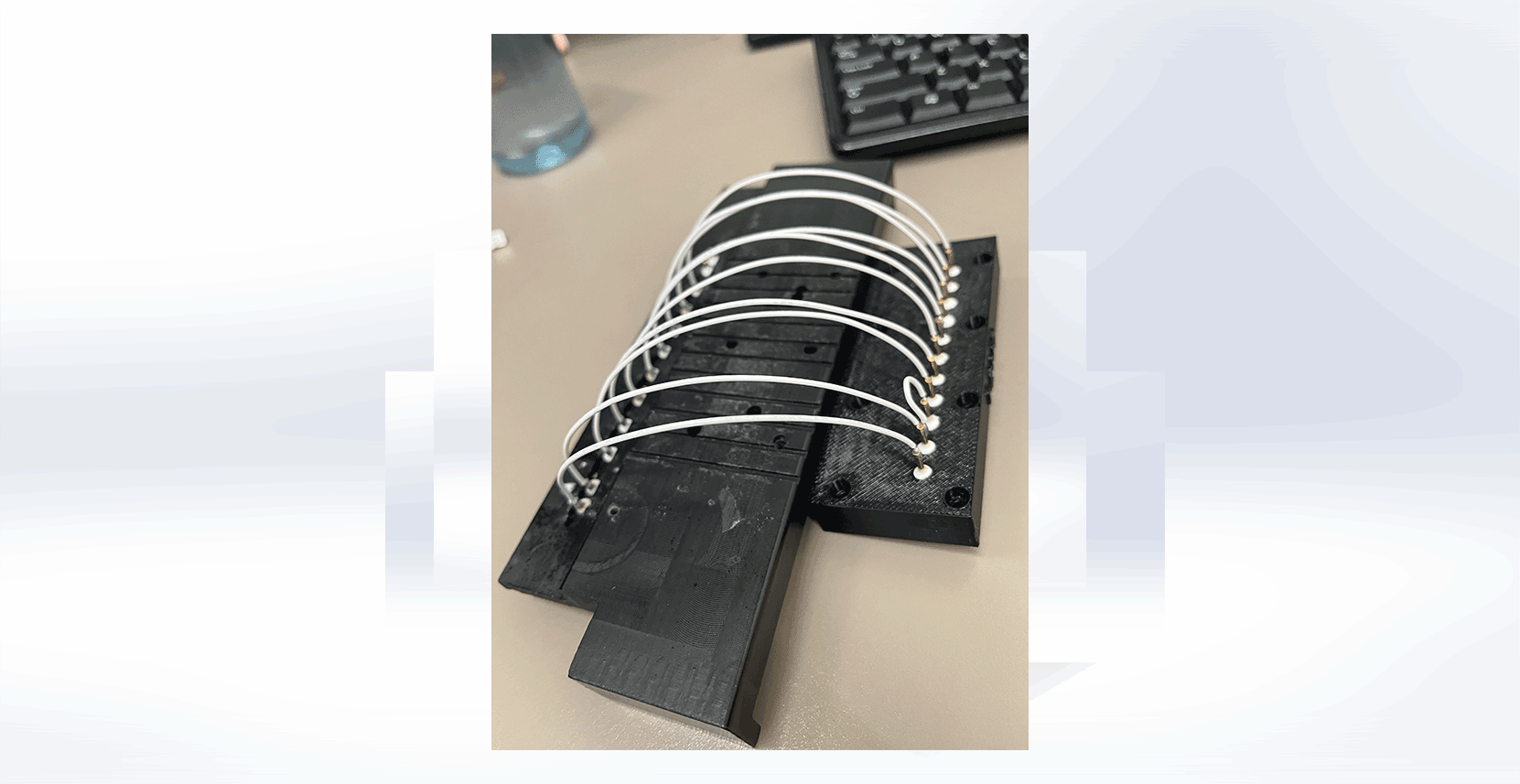
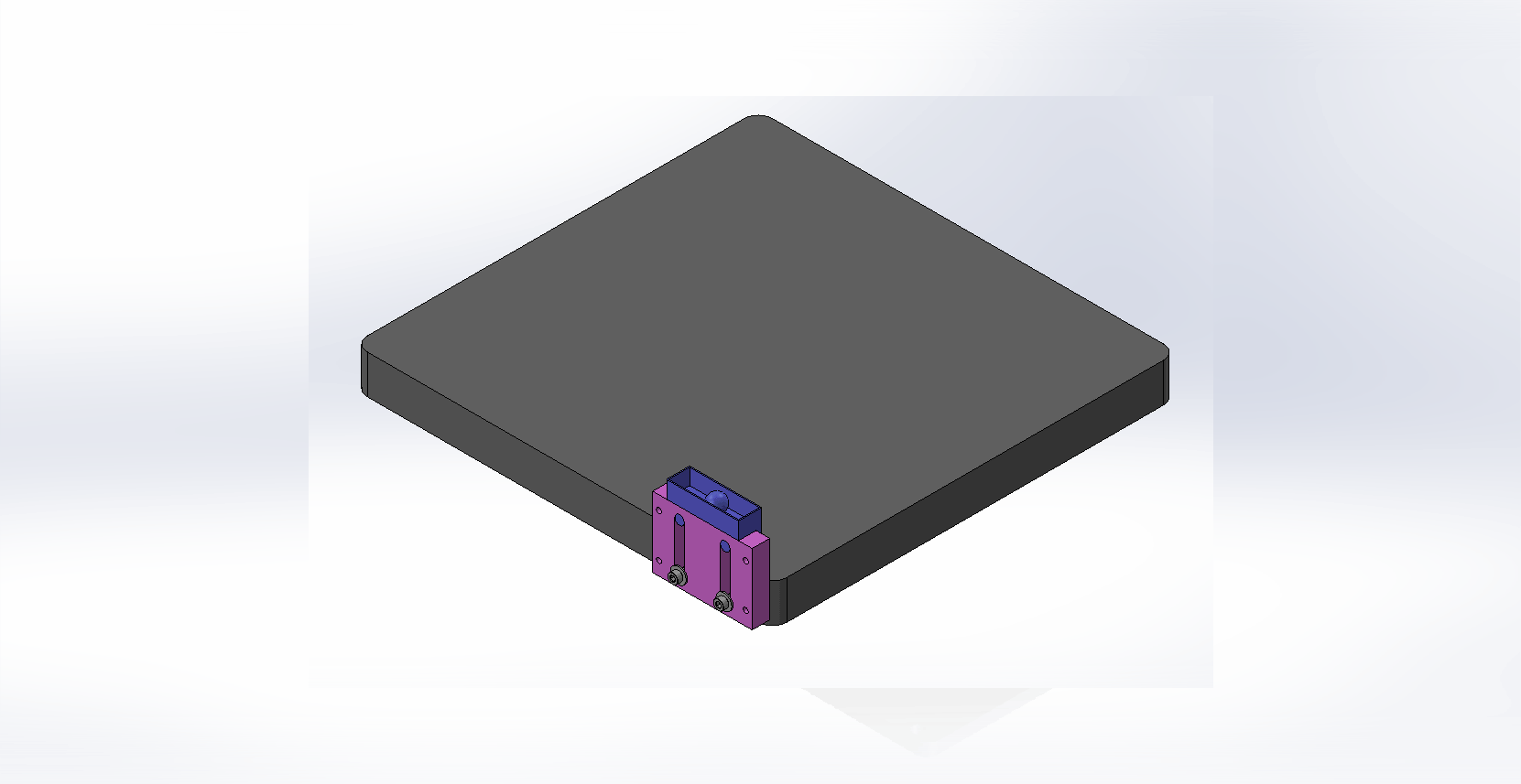
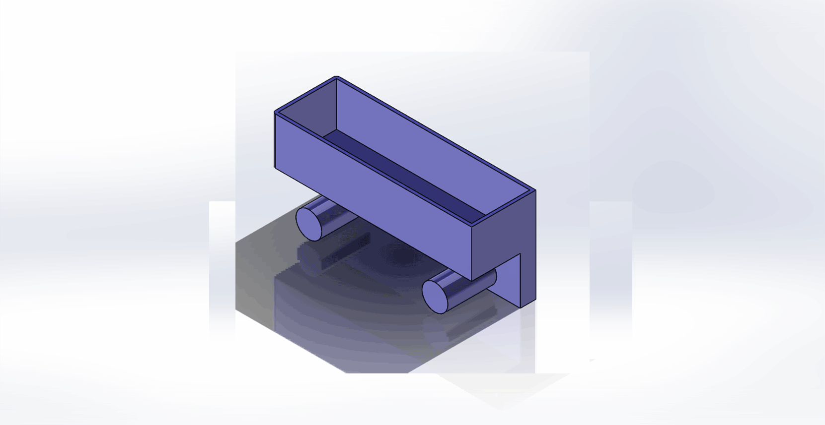
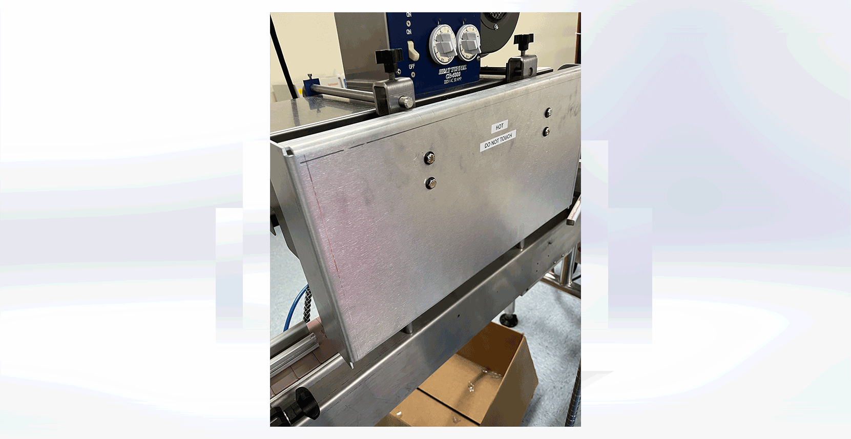
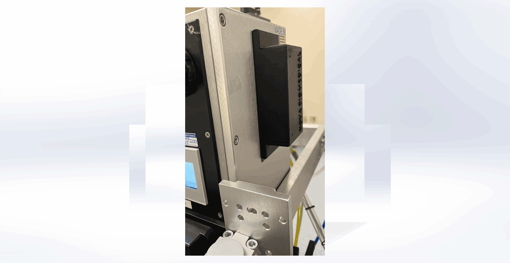
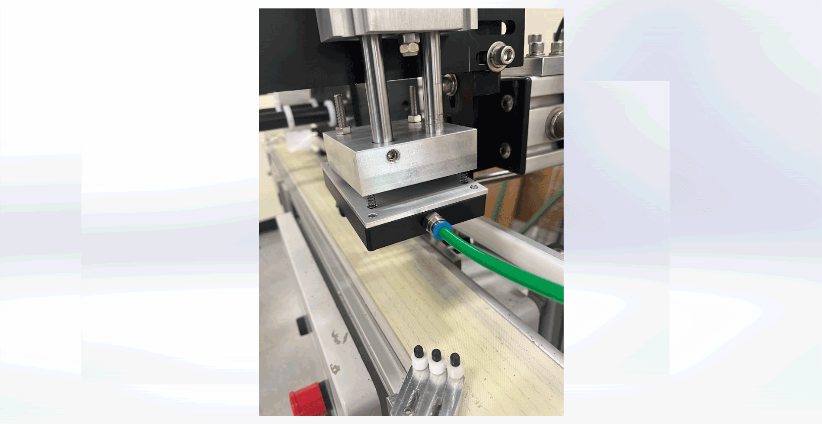
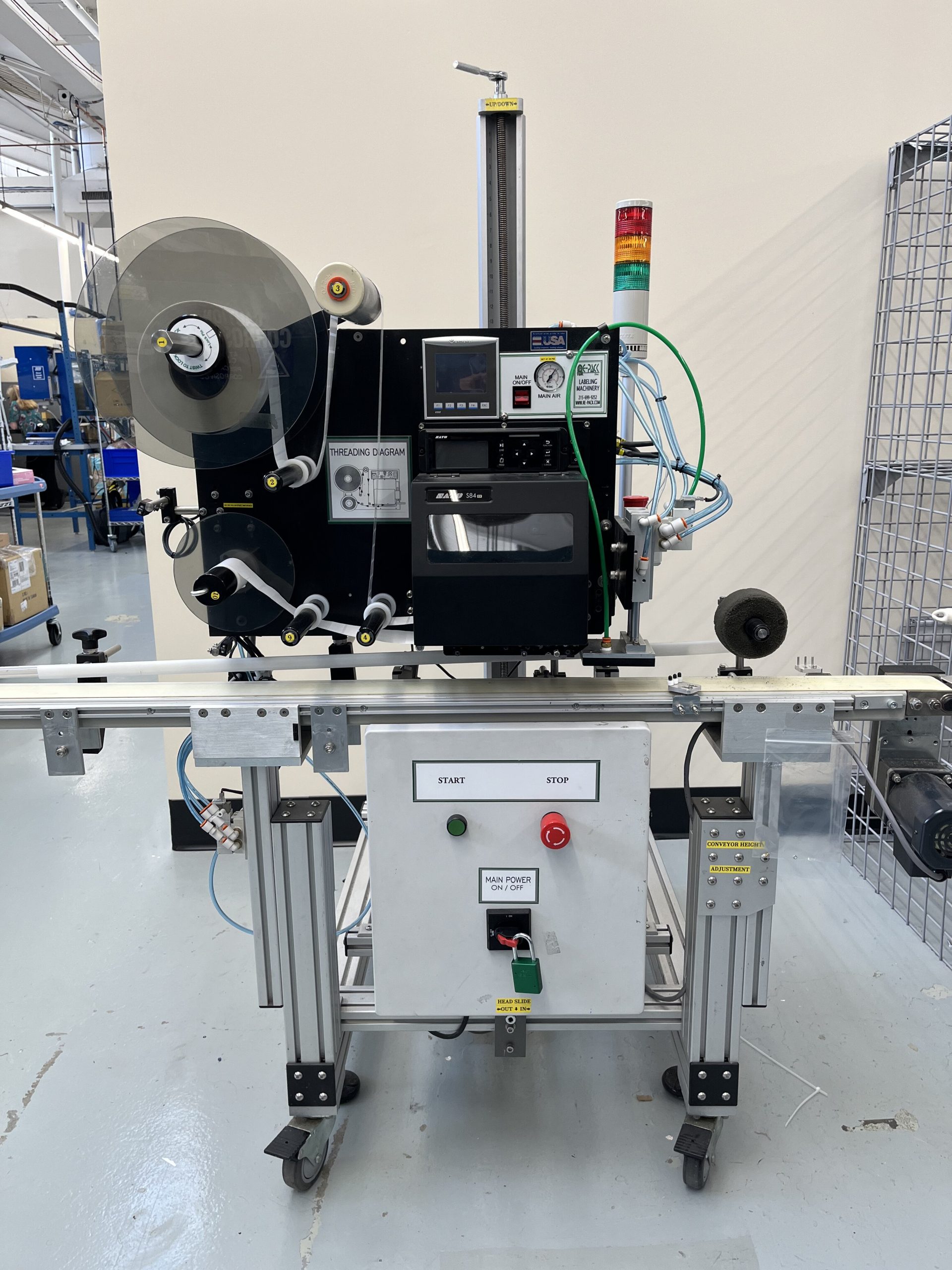
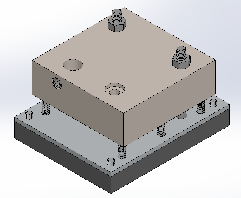
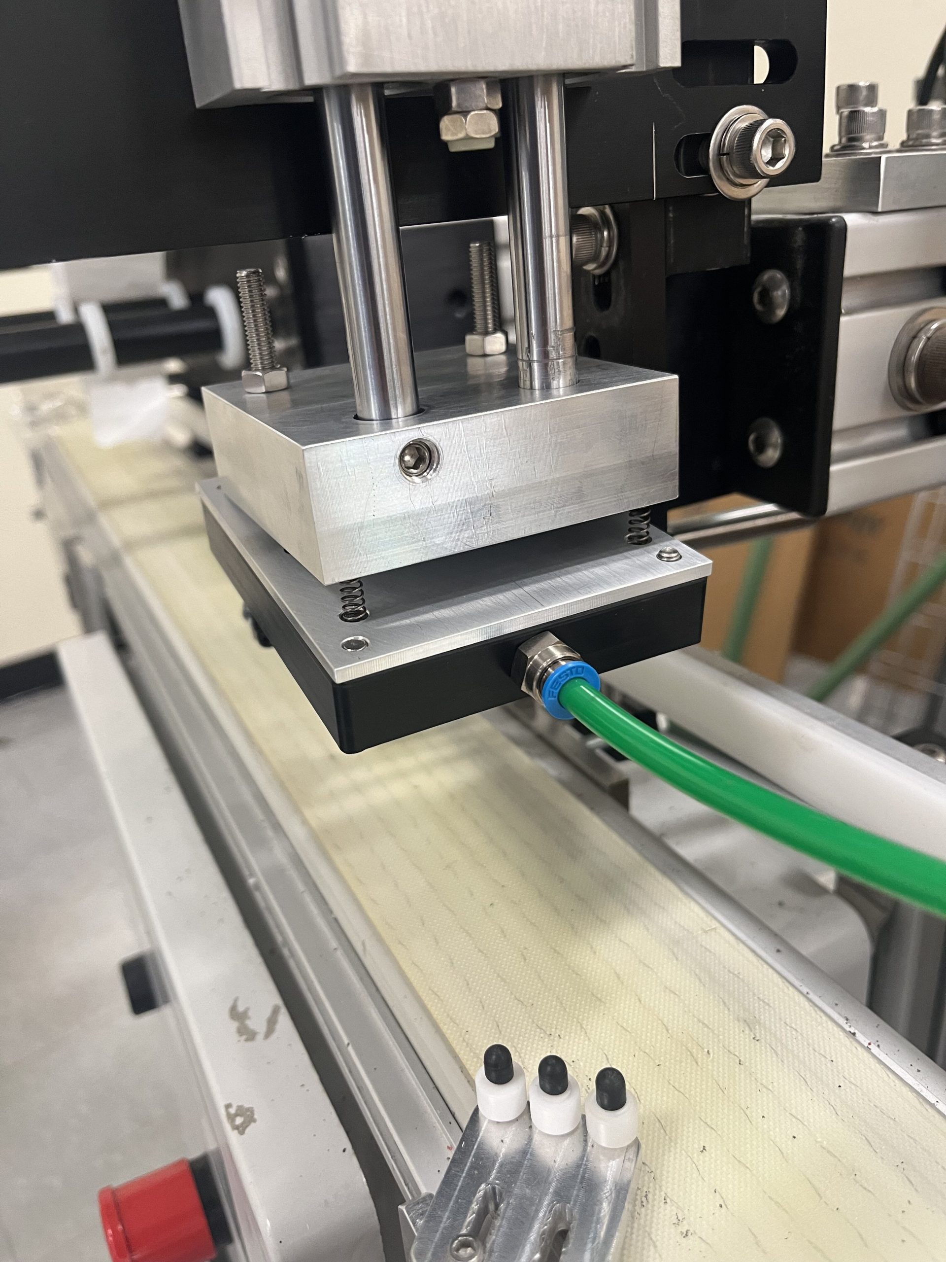
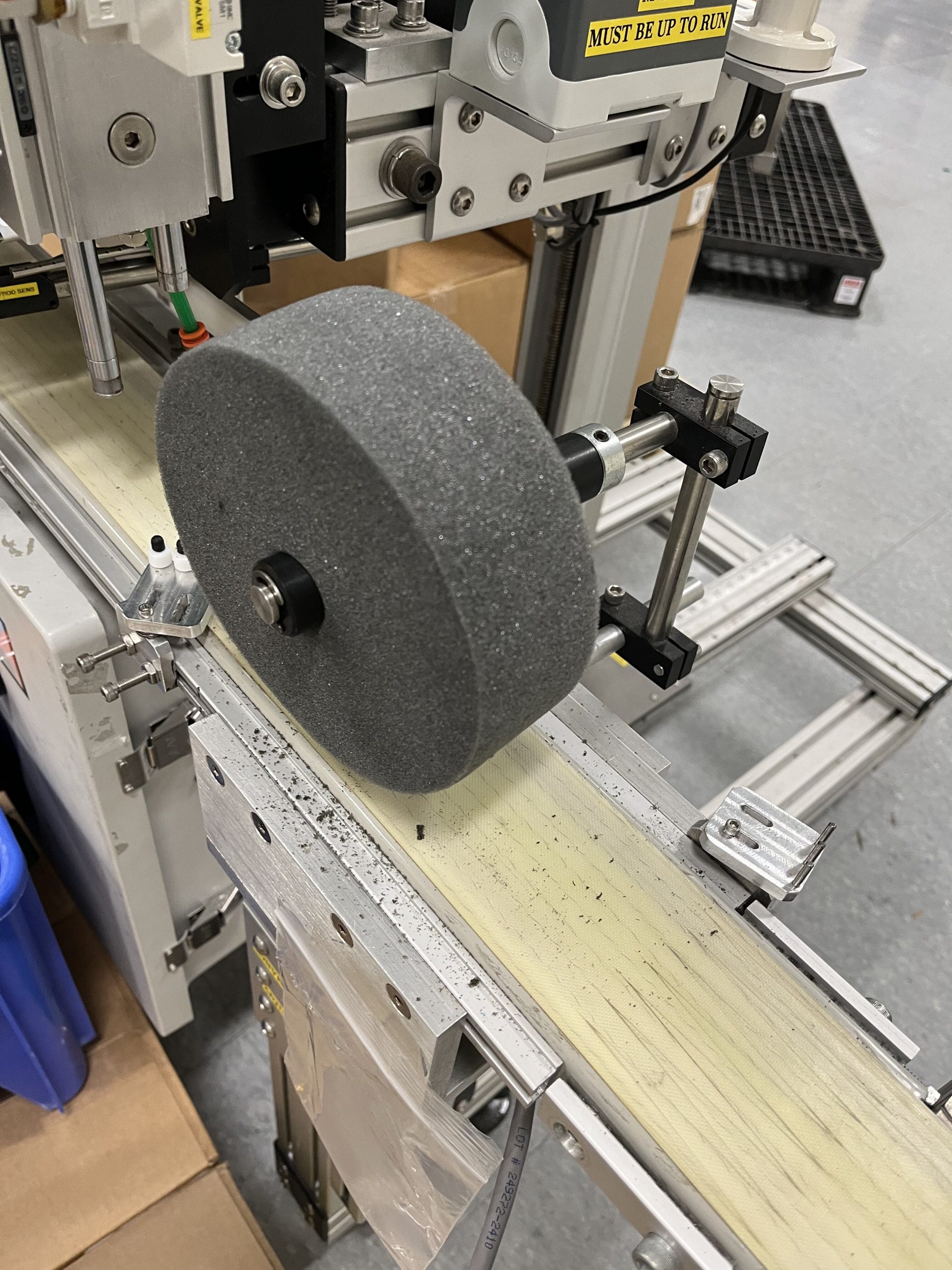
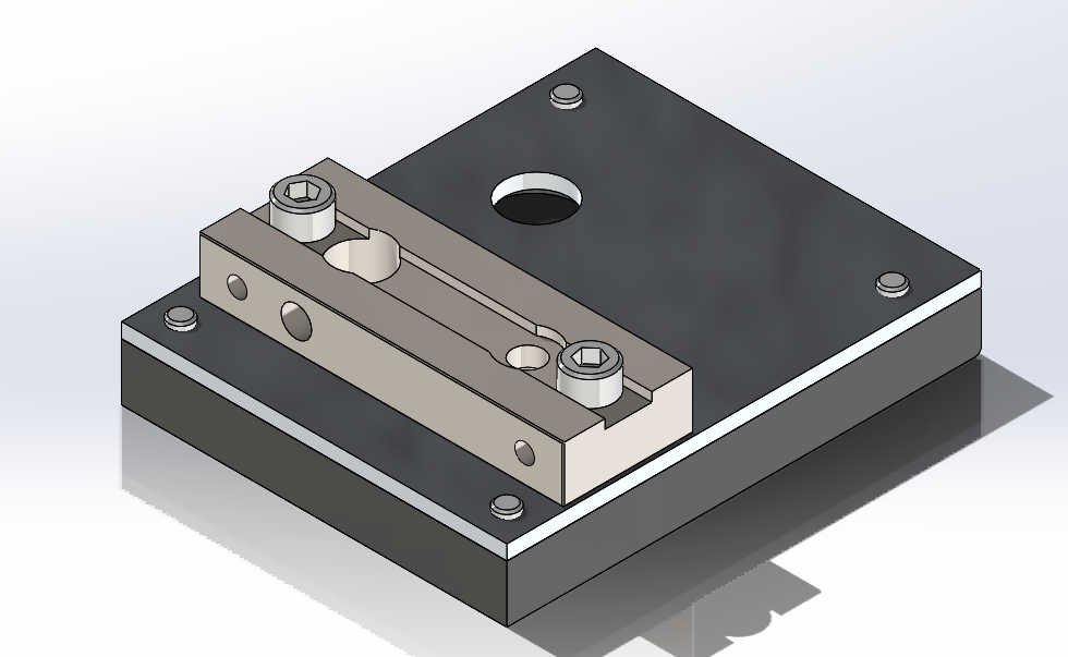
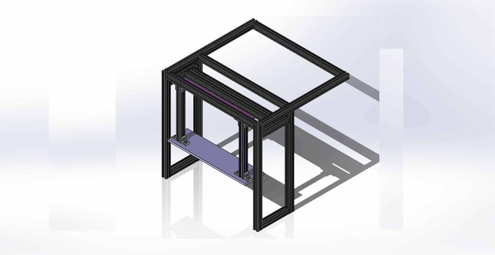
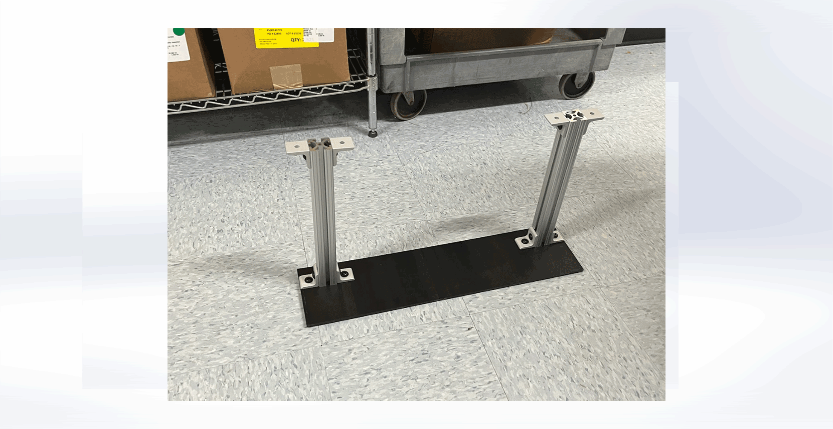
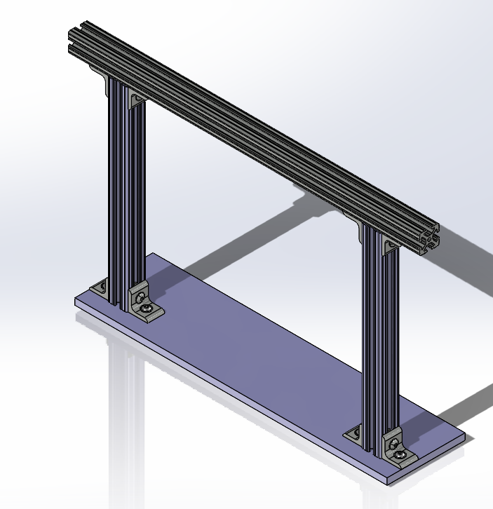
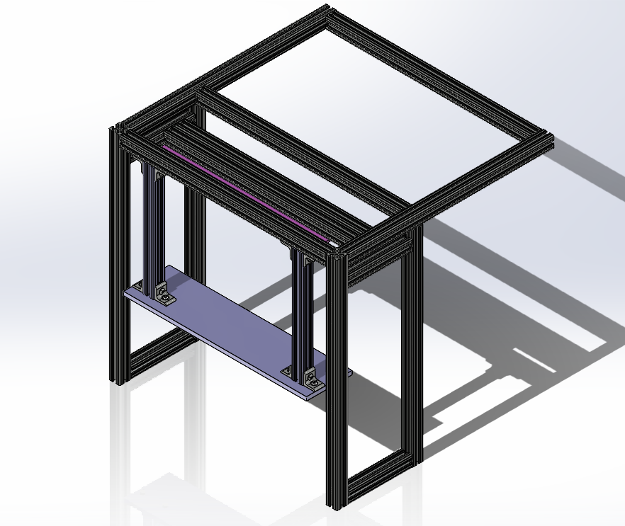
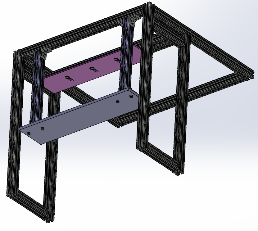
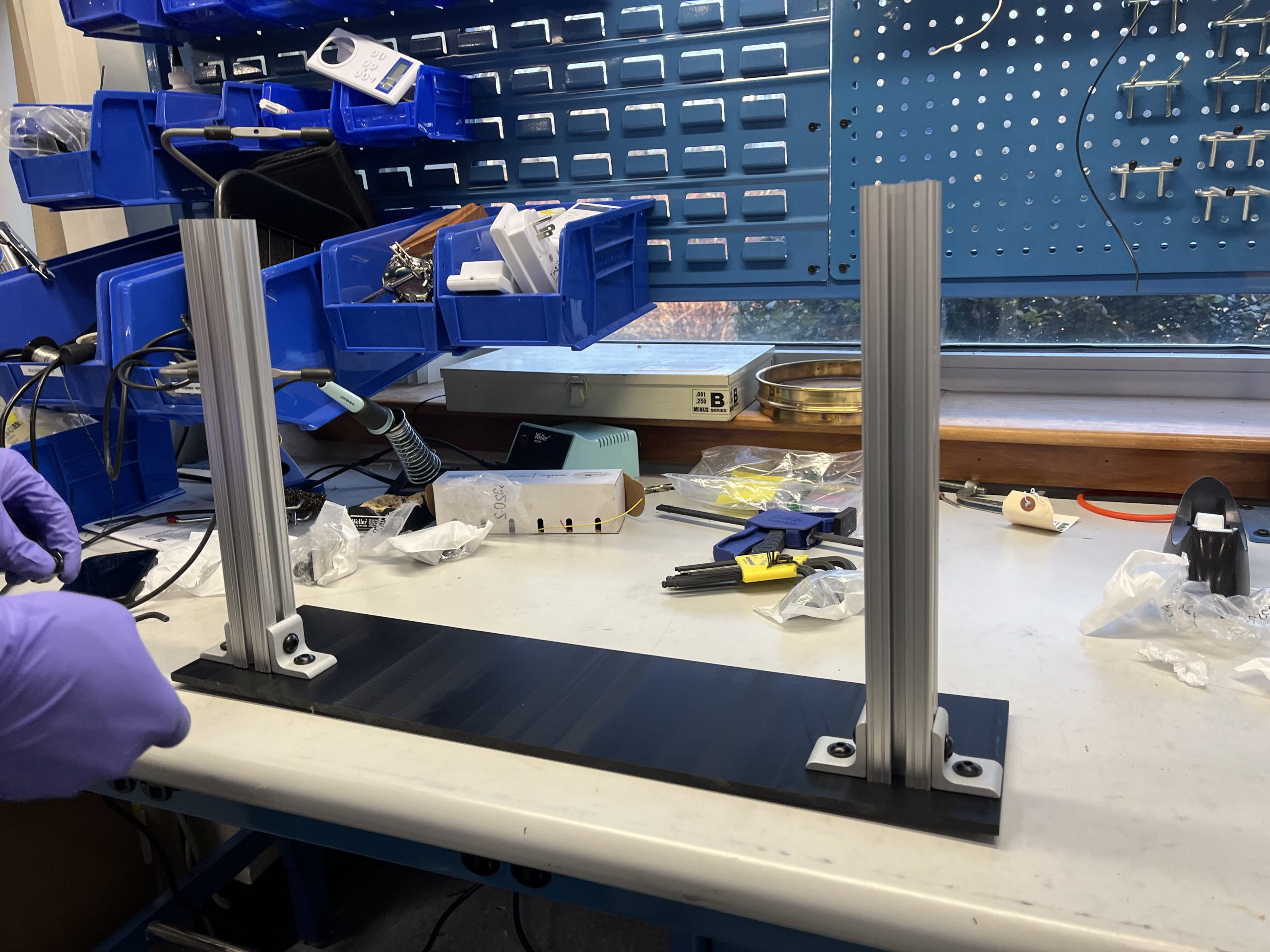
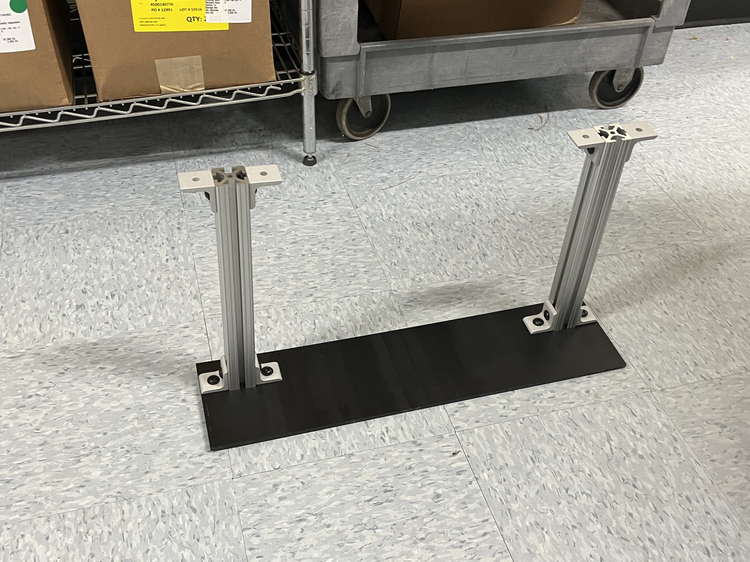
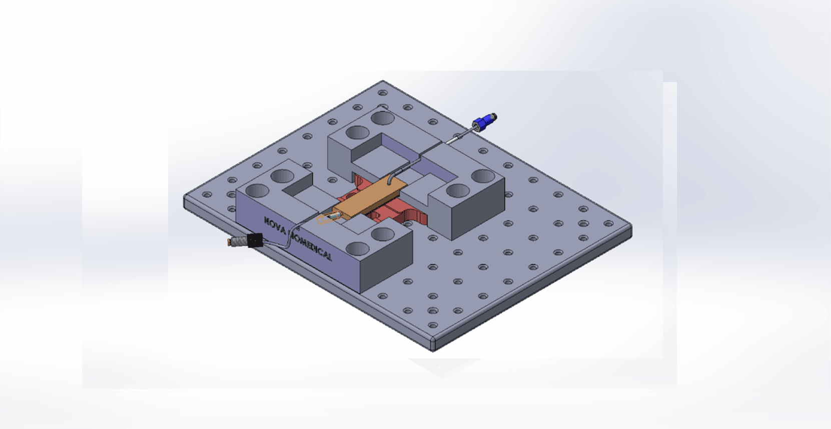
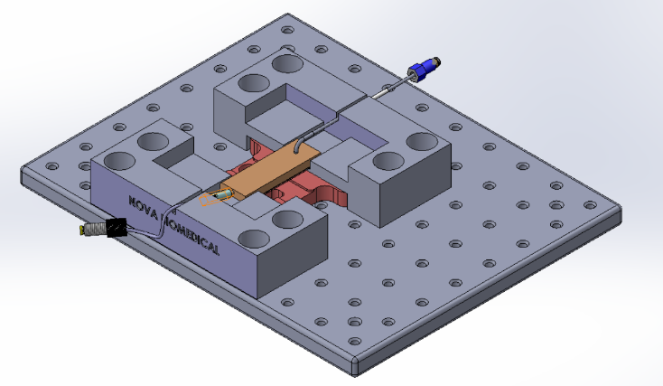
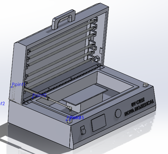
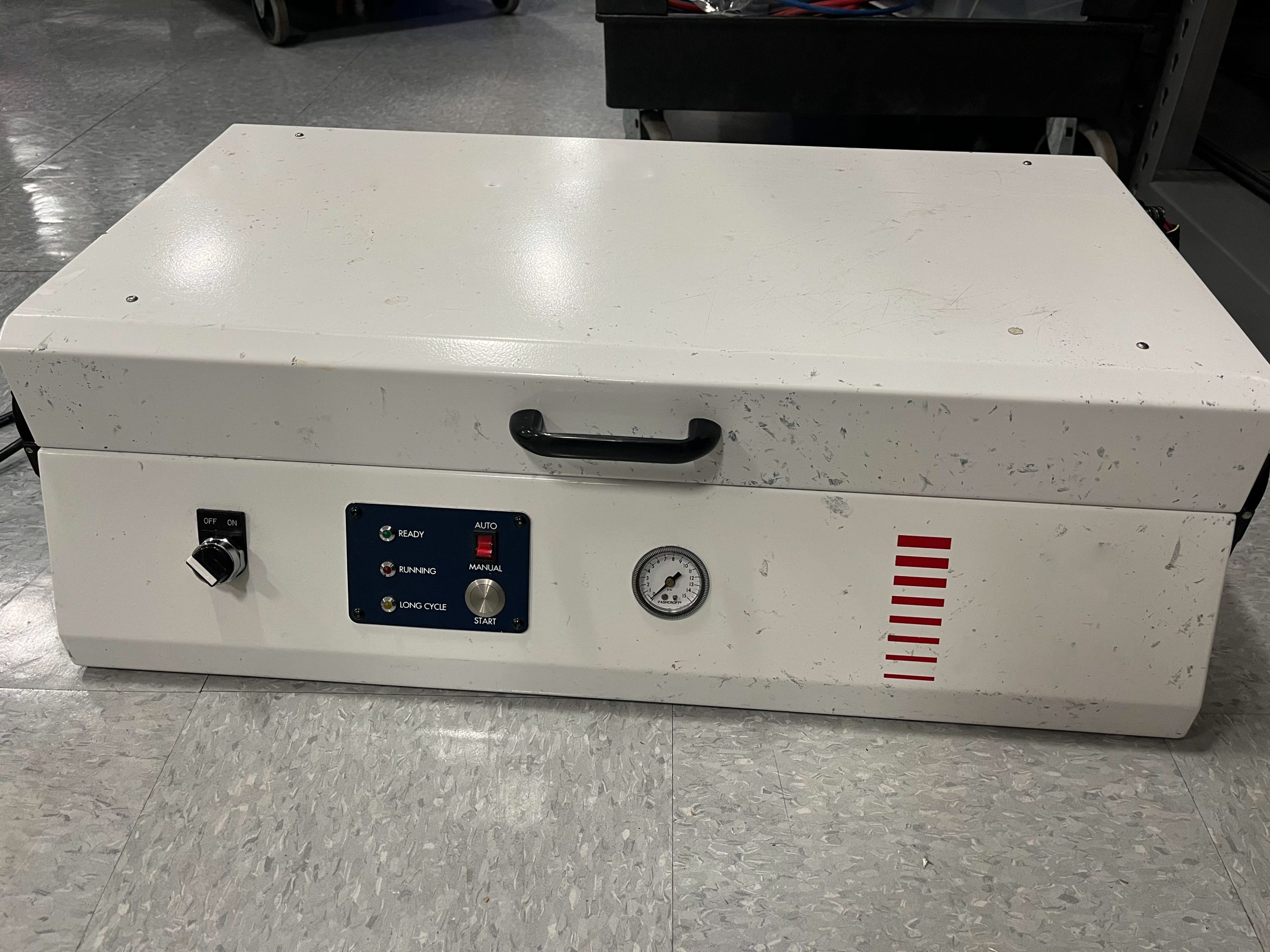
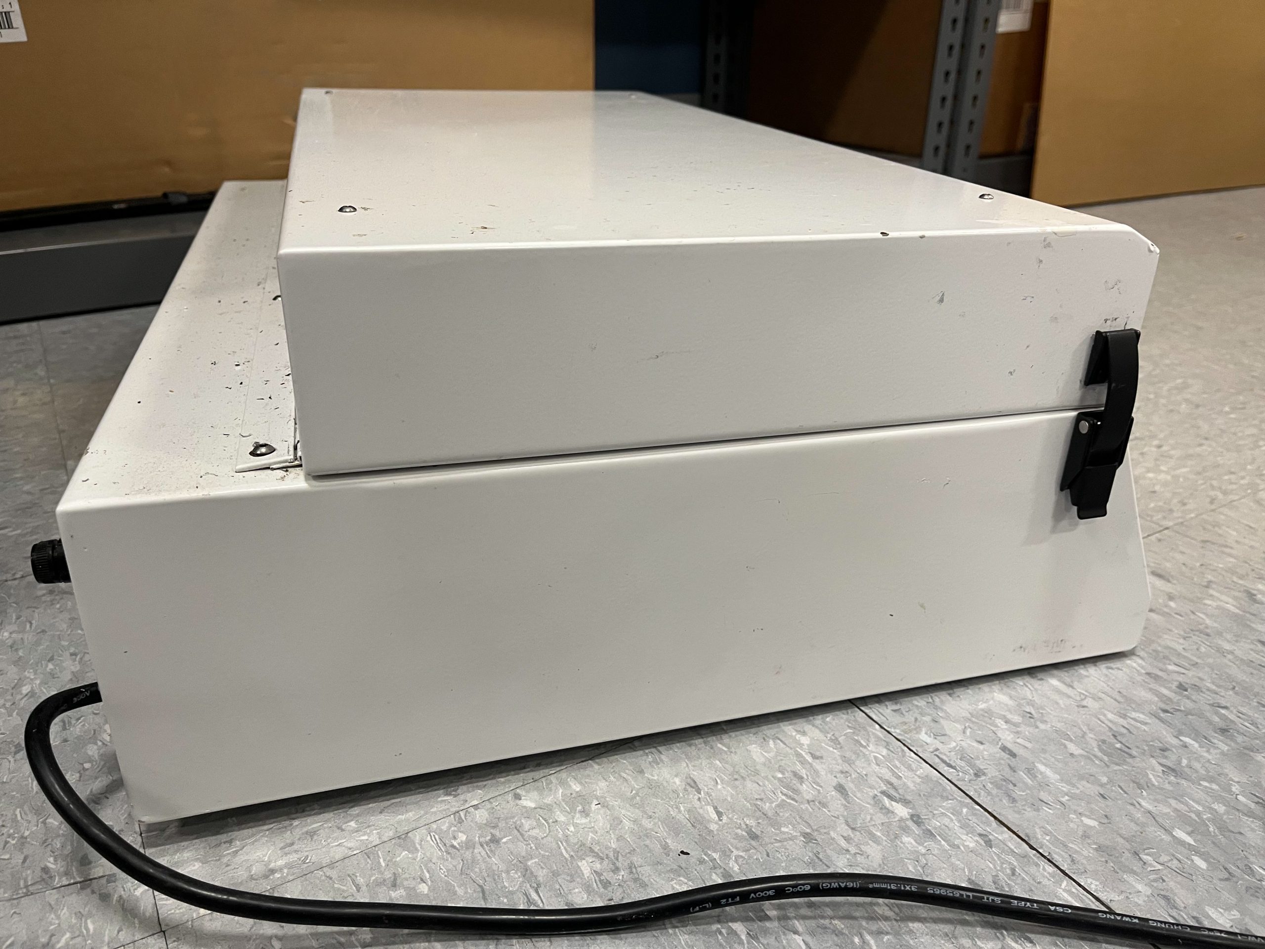
Resistor Cutter Assembled